Learning embedded Rust by building RISC-V-powered robot - Part 3
In the previous part, we were able to control the servo motor by writing to PWM registers of the FE310 microcontroller. Now it’s time to have more fun with Rust by writing high-level servo motor abstraction that is suitable for controlling multiple servo motors in a uniform fashion.
The HAL expresses such abstractions as Rust traits with the goal of making code more portable between different embedded platforms.
The core functionality of the servo motor is captured in the Servo trait.
struct Degrees(f64);

trait F64Ext {
    fn degrees(self) -> Degrees;
}

impl F64Ext for f64 {
    fn degrees(self) -> Degrees {
        if self > 180.0 || self < 0.0 {
            panic!("Invalid angle");
        }
        Degrees(self)
    }
}

trait Servo {
    fn read(&self) -> Degrees;
    fn write(&self, degrees: Degrees) -> ();
}
In addition to read and write functions, we define the Degrees type that wraps f64 with additional runtime check. If degrees value is out of range, we want our program to panic instead of stripping the gears of our servo motor!
Since Rust HAL represents each pin and each PWM device by the dedicated type, we must use these types as generic arguments in servo structure definition. Besides pin and PWM, we also need duty values at 0 and 180 degrees positions. Letting each instance to have duty values makes it possible to calibrate each servo motor independently.
struct PwmServo<'a, TPin, TPWM> {
    _pin: TPin,
    pwm: &'a TPWM,
    duty_at_0_degrees: u16,
    duty_at_180_degrees: u16,
}
Note that the pin field isn’t used after the PwmServo instance is constructed, but we need the PwmServo instance to own it, so the structure declares it as _pin to silence the warning. On the contrary, the PwmServo instance only references the PWM device, and for this to compile, we need to parametrize it with the lifetime 'a.
trait PwmServoConstructor<'a, TUnknownPin, TPwmPin, TPWM> {
    fn new(
        pin: TUnknownPin,
        pwm: &'a TPWM,
        duty_at_0_degrees: u16,
        duty_at_180_degrees: u16,
    ) -> PwmServo<'a, TPwmPin, TPWM>;
}
In addition to the structure, we need to define the PwmServoConstructor trait that allows the compiler to pick the right new function based on argument types, as you will see later. Note how the 'a lifetime parameter ties the PWM reference to the PwmServo instance returned by the new function. Also, here we need separate parameters for TUnknownPin and TPwmPin since into_inverted_iof1 function changes pin type.
impl
    PwmServoConstructor<
        '_,
        gpio0::Pin20<Unknown>,
        gpio0::Pin20<IOF1<Invert>>,
        PWM1,
    > for PwmServo<'_, gpio0::Pin20<IOF1<Invert>>, PWM1>
{
    fn new(
        pin: gpio0::Pin20<Unknown>,
        pwm: &PWM1,
        duty_at_0_degrees: u16,
        duty_at_180_degrees: u16,
    ) -> PwmServo<'_, gpio0::Pin20<IOF1<Invert>>, PWM1> {
        pwm.cfg
            .write(|w| unsafe { w.enalways().bit(true).scale().bits(6) });

        PwmServo {
            _pin: pin.into_inverted_iof1(),
            pwm: pwm,
            duty_at_0_degrees,
            duty_at_180_degrees,
        }
    }
}
The new function implementation is relatively involved. Since pin and PWM types do not implement common traits, we need to define a dedicated new function for every pin and PWM type so that the compiler can check everything out.
Also note that it is defined for Pin20, which is different from pin 4 (dig4) that we connected the servo motor to. The reason is that dig4 declaration comes from the HiFive1 board crate, and the HiFive1 board connects it to the pin 20 on the FE310 GPIO. Our servo library is HAL-level and may be reused with different FE310 boards letting the compiler check that the right board pins are passed! Finally, the pin and PWM configuration are now part of the new function.
impl Servo for PwmServo<'_, gpio0::Pin20<IOF1<Invert>>, PWM1> {
    fn read(&self) -> Degrees {
        duty_to_degrees(
            self.duty_at_0_degrees,
            self.duty_at_180_degrees,
            self.pwm.cmp0.read().value().bits(),
        )
    }

    fn write(&self, degrees: Degrees) -> () {
        self.pwm.cmp0.write(|w| unsafe {
            w.value().bits(degrees_to_duty(
                self.duty_at_0_degrees,
                self.duty_at_180_degrees,
                degrees,
            ))
        });
    }
}
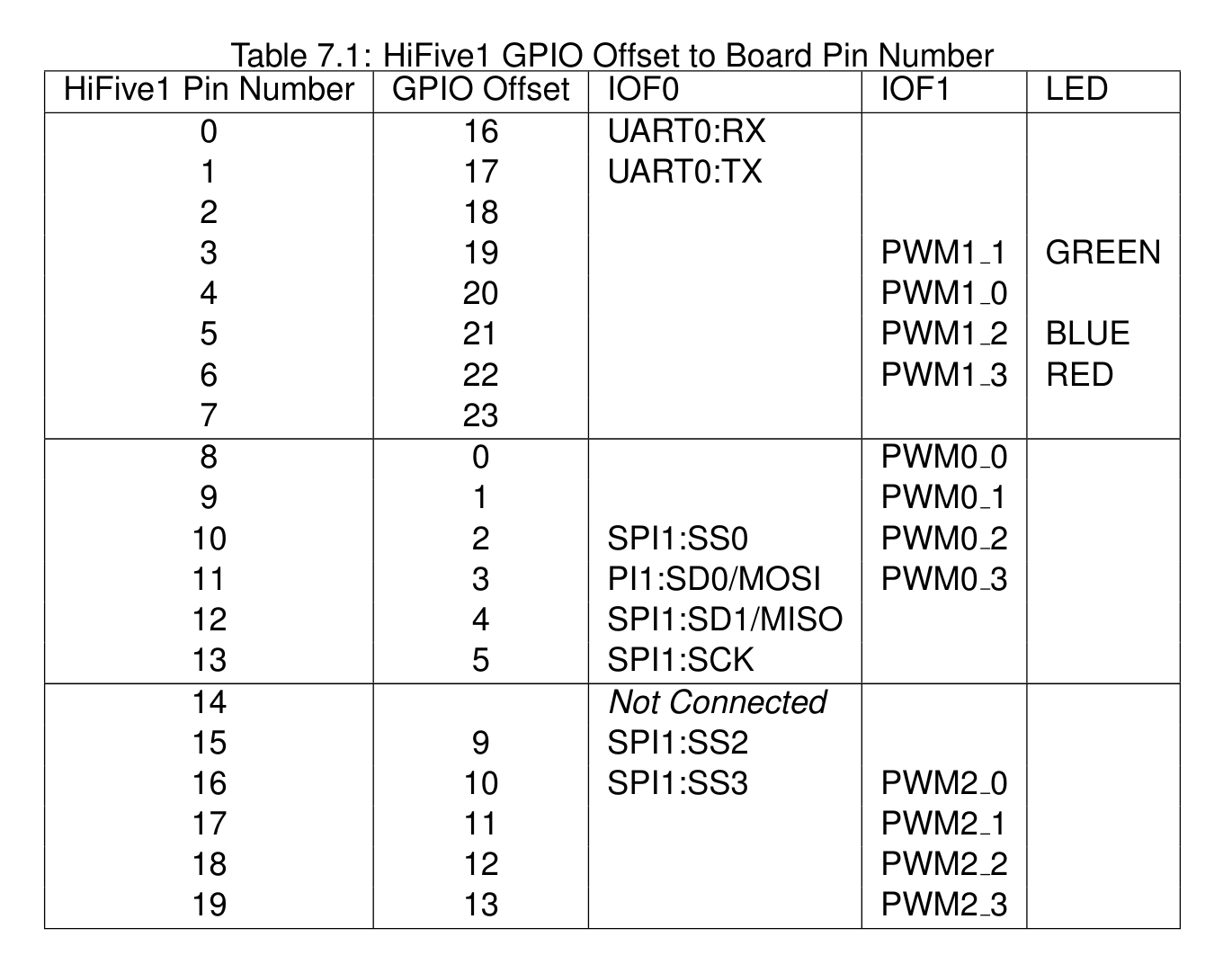
The same specialization requirement applies to read and write functions to capture the relationship between GPIO pin 20, PWM1, and channel 0 (cmp0). The refined version of this code may use macros to reduce duplication, but we won’t do this here. The following table from the HiFive1 getting started guide summarizes these relationships.
Finally, we define helper functions to translate duty to degrees and vice versa.
fn degrees_to_duty(
    duty_at_0_degrees: u16,
    duty_at_180_degrees: u16,
    degrees: Degrees,
) -> u16 {
    (duty_at_0_degrees as f64
        + ((degrees.0 / 180.0)
            * (duty_at_180_degrees - duty_at_0_degrees) as f64)) as u16
}

fn duty_to_degrees(
    duty_at_0_degrees: u16,
    duty_at_180_degrees: u16,
    duty: u16,
) -> Degrees {
    Degrees(
        ((duty - duty_at_0_degrees) as f64
            / (duty_at_180_degrees - duty_at_0_degrees) as f64)
            * 180.0,
    )
}
With this in place, we can rewrite the loop to work with four servo motors and both PWMs at the same time by calling Servo trait write function polymorphically.
let servos: [&dyn Servo; 4] = [
    &PwmServo::new(pin!(pins, dig4), &pwm1, 3277, 6554),
    &PwmServo::new(pin!(pins, dig3), &pwm1, 3277, 6554),
    &PwmServo::new(pin!(pins, dig16), &pwm2, 3277, 6554),
    &PwmServo::new(pin!(pins, dig17), &pwm2, 3277, 6554)
];

loop {
    sleep.delay_ms(1000u32);

    for servo in servos.iter() {
        servo.write(0.0.degrees());
    }

    sleep.delay_ms(1000u32);

    for servo in servos.iter() {
        servo.write(180.0.degrees());
    }
}
Note that if we try to create PwmServo for the wrong pin or PWM, the code won’t compile. Also, if we accidentally instantiate more than one PwmServo for the same pin, it won’t compile either!
And, the four servos are turning in-sync!
You can see the entire source code for this part on GitHub.
In the final part, we will complete the remaining abstractions needed to animate the spider robot and see it in action!