Learning embedded Rust by building RISC-V-powered robot - Part 2
The ALLBOT spider uses the 9G servo motors to animate its legs. The Arduino implementation uses a built-in servo library that allows assigning servo instance to a pin and then writing desired orientation degrees between 0 and 180. The e310x HAL does not have servo implementation, nor the Embedded HAL have the servo trait. Time to face the hardware at the lowest level!
The first thing is to find the datasheet for the 9G servo motor. The datasheet summarizes the entire servo interface in one simple diagram!
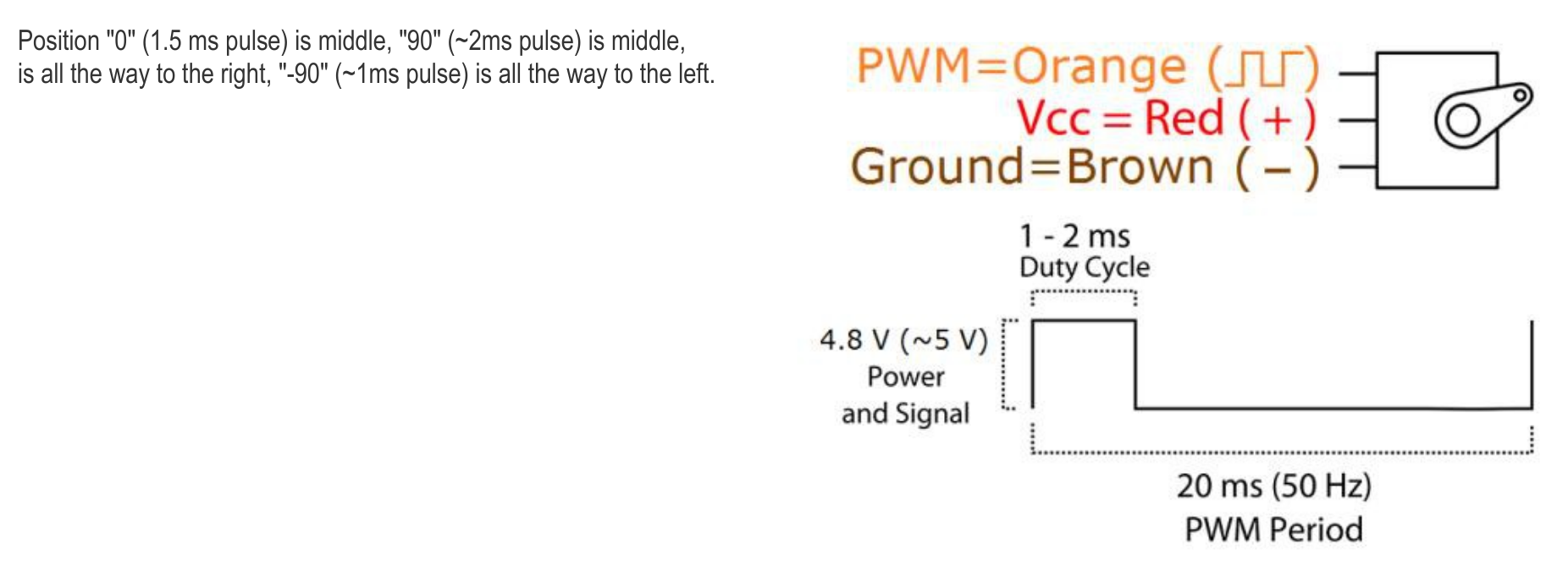
Servo’s angle is controlled by a continuous pulse that occurs every 20 milliseconds (50Hz) and lasts between 1 and 2 milliseconds. The desired angle is encoded within this range. The 0 degrees corresponds to 1 millisecond and 180 degrees to 2 milliseconds. That simple!
The ability to produce a digital signal with a defined modulation (period) and duty cycles (the fraction of the modulation cycle when the signal level is “active”) is called Pulse-Width Modulation (PWM). The FE310 microcontroller has dedicated peripherals for producing PWM signals. The manual explains the PWM operation in great detail.
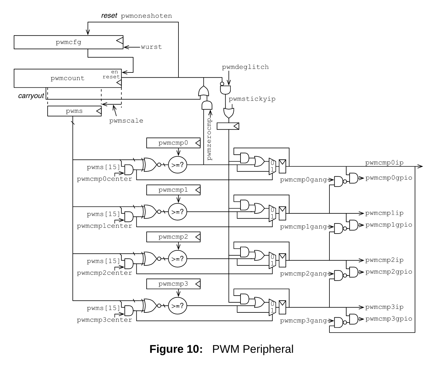
Each FE310 chip has 3 independent pulse-width modulator devices. Each such device is capable of supporting 3 or 4 PWM channels depending on the mode. Everything starts with a counter that increments with every clock tick. This counter is accessible via pwmcounter register. The pwmcounter is then scaled, or divided, by configurable 4-bit pwmscale value and truncated into scaled counter pwms. The schematics from the manual explains this visually.
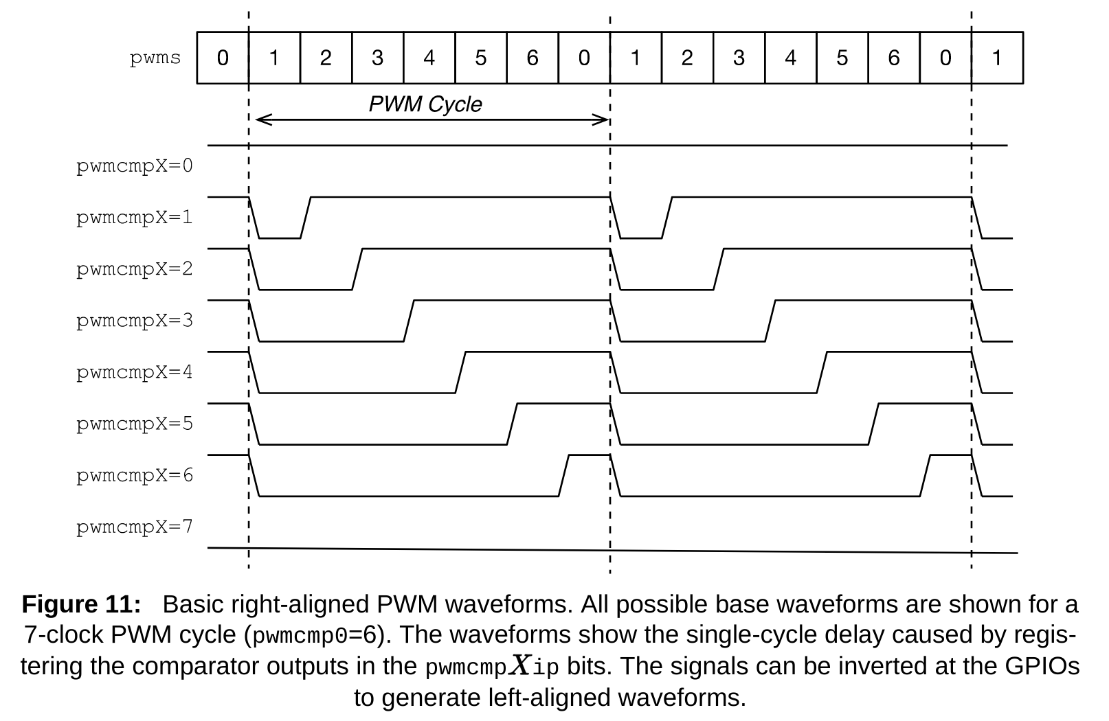
Once the pwms counter gets to 0, on the next counter tick, the new PWM cycle starts. The duty cycle for each of the 4 outputs is controlled by a corresponding pwmcmpX comparator register. The PWM cycle starts with a “0” level. When pwms becomes greater or equal to pwmcmpX, on the next counter tick, the level goes to “1”. This condition corresponds to the negative duty cycle, but luckily the FE310 can be programmed to invert this signal at the GPIO pin. The following timing diagram explains this visually.
There are two modes of how pwms register gets reset to 0.
In the “precise” mode, the PWM cycle can be controlled precisely at the cost of reducing the number of PWM channels by 1. This control is achieved by reserving the pwmcmp0 comparator register to be the maximum value for pwms. This mode is enabled by setting pwmzerocmp in the PWM configuration word.
In the “wrapping” mode, pwms register simply wraps. This way, the counter width, the scaling factor, and the clock speed define the PWM cycle width.
Finally, FE310’s PWM devices differ in bit width. The PWM0 has 8-bit long pwms counter and the comparator registers, and 23-bit long pwmcounter register. PWM1 and PWM2 are 16-bit. They have a 31-bit long pwmcounter register.
The ALLBOT spider uses 8 servos–2 servos for each of 4 legs. Therefore we need 8 PWM channels.
The 8-bit PWM0 provides the maximum resolution of 256 for controlling the duty cycle. Given 9G servo uses a 5% difference in the duty cycle for controlling the angle, we have only 12.8 counter ticks, and the precision of 180 ÷ 12.8 = 14 degrees per counter tick, which is somewhat limiting. Therefore we have to utilize PWM1 and PWM2 in the “wrapping” mode to get 8 channels in total.
Following the same calculation, we get a precision of 0.054 degrees per counter tick for the 16-bit PWMs. Great!
Now, let’s see if we can get a 20 millisecond PWM cycle by playing with the core clock frequency and scaling factor.
50 Hz × 2^(16 + X) = Y, where X is the scaling factor, and Y the desired core clock frequency. The first highest clock speed that is under the 320MHz limit is Y = 209.7MHz. The corresponding scaling factor is X = 6.
How close can we get to 209.7MHz core clock? The answer in how the FE310 sets its core clock based on an external oscillator using the Phased-locked loop (PLL). The following is the PLL ratios diagram from the FE310 manual.
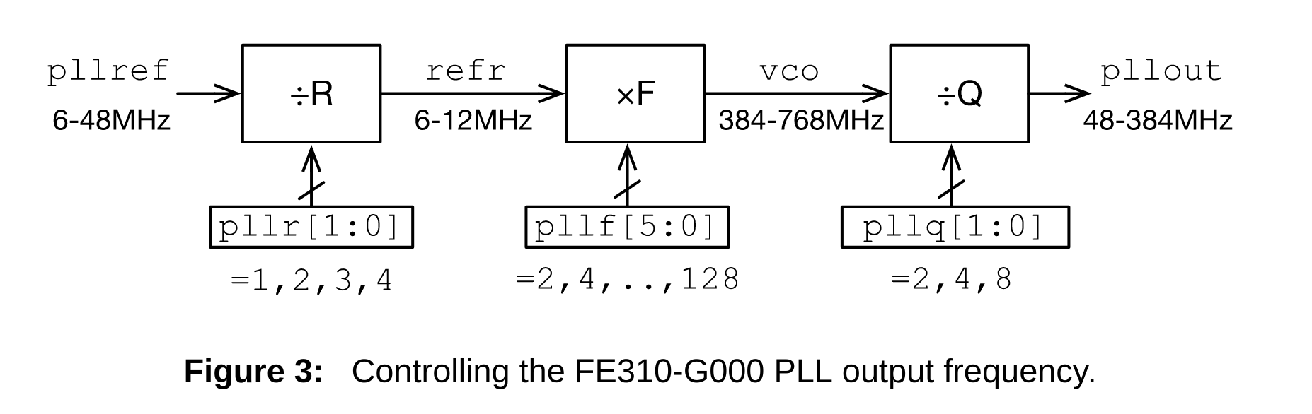
The pllref provided by the HiFive1 on-board oscillator is 16MHz. The e310x HAL takes the desired core frequency that we pass to hifive1::clock::configure function and computes the values for R, F, and Q to get close to the desired pllout value. For 209.7MHz these values are R = 2, F = 52, and Q = 2. And the actual core frequency is 208MHz. Is this close enough?
208MHz ÷ 2^(16 + 6) = 49.59Hz is the actual PWM cycle. Will this work? The only way to tell is to get our hands dirty and try this with the real servo motor.
To calculate the comparator values for the duty cycle, we assume our PWM cycle is ideal and deal in fractions instead of absolute time.
20,000 ÷ 2^16 = 0.305 is the resolution in microseconds per counter tick. This way, to set the servo to 0 degrees, we set the counter register to 1000 ÷ 0.305 = 3277 and for 180 degrees to 2000 ÷ 0.305 = 6554.
Now that we are done with back-of-the-envelope research let’s write some Rust!
#![no_std]
#![no_main]

extern crate panic_halt;

use hifive1::hal::delay::Sleep;
use hifive1::hal::device::DevicePeripherals;
use hifive1::hal::prelude::*;
use hifive1::hal::DeviceResources;
use hifive1::pin;
use riscv_rt::entry;

#[entry]
fn main() -> ! {
    let DeviceResources {
        core_peripherals,
        peripherals,
        pins,
        ..
    } = DeviceResources::take().unwrap();
    let DevicePeripherals {
        PRCI: prci,
        AONCLK: aonclk,
        PWM1: pwm1,
        ..
    } = peripherals;

    let clocks = hifive1::clock::configure(prci, aonclk, 208.mhz().into());
    let mut sleep = Sleep::new(core_peripherals.clint.mtimecmp, clocks);

    pin!(pins, dig4).into_inverted_iof1();

    pwm1.cfg
        .write(|w| unsafe { w.enalways().bit(true).scale().bits(6) });

    loop {
        sleep.delay_ms(1000u32);
        pwm1.cmp0.write(|w| unsafe { w.value().bits(3277) });

        sleep.delay_ms(1000u32);
        pwm1.cmp0.write(|w| unsafe { w.value().bits(6554) });
    }
}
First, we have the familiar clock configuration, except we set the desired core frequency to 208MHz.
pin!(pins, dig4).into_inverted_iof1(); Here we configure the pin that is attached to channel 0 of the PWM1 to connect to the IO function #1, which is the PWM.
Next, we use write function from e310x PAC to write to PWM1 cfg register. Specifically, we set enalways bit to enable the PWM and set the scale bits to 6. The svd2rust tool defines the structure for read, modify, and write functions that are generated for the PAC.
In the loop, we alternatively write 3277 and 6554 to the PWM1 cmp0 register to change the servo angle correspondingly to 0 and 180 degrees. We include a 1-second delay to give the servo time to change the position.
And… the servo it turning!
You may have noticed that the servo is not turning the entire 180 degrees range. It turns out the datasheet duty cycle specification is very approximate, and depending on the servo maker and even the individual servo motor, it is different. The approach here is to calibrate the range for the servo you have by making sure it turns almost to the limit. But be careful, turning over the limit may strip the gears!
With that, we wrap part 2. In the next part, we will write a HAL-level abstraction for servo motor capable of animating multiple servo motors synchronously.