Building speech controlled robot with Tensil and Arty A7 - Part II
Introduction
This is part II of a two-part tutorial in which we will continue to learn how to build a speech controlled robot using Tensil open source machine learning (ML) acceleration framework, Digilent Arty A7-100T FPGA board, and Pololu Romi Chassis. In part I we focused on recognizing speech commands through a microphone. Part II will focus on translating commands into robot behavior and integrating with the Romi chassis.
System architecture
Let’s start by reviewing the system architecture we introduced in Part I. We introduced two high-level components: Sensor Pipeline and State Machine. Sensor Pipeline continuously receives the microphone signal as an input and outputs events representing one of the four commands. State Machine receives a command event and changes its state accordingly. This state represents what the robot is currently doing and is used to control the engine.

First, we will work on the State Machine and controlling the motors. After this we will wire it all together and assemble the robot on the chassis.

State Machine
The State Machine is responsible for managing the current state of the motors. It receives command events and depending on the command changes the motor’s state. For example, when it receives the “go!” command it turns both motors in the forward direction; when it receives the “right!” command it turns the right engine in the backward direction and the left engine in the forward direction.
The Sensor Pipeline produces events containing a command and its prediction probability. As we mentioned before the ML model is capable of predicting 12 classes of commands, from which our robot is using only 4. So, firstly, we filter events for known commands. Secondly, we use a per-command threshold to filter for sufficient probability. During testing these thresholds can be adjusted to find the best balance between false negatives and false positives for each command.
By experimenting with the Sensor Pipeline we can see that it may emit multiple events for the same spoken command. Usually, the series of these instances includes the same predicted command. This happens because the recognition happens on a sliding window where the sound pattern may be included in several consecutive windows. Occasionally, the series starts with a correctly recognized command and is then followed by an incorrect one. This happens when a truncated sound pattern in the last window gets mispredicted. To smooth out these effects we introduce a “debouncing” state. The debouncing state prevents changing the motor’s state for a fixed period of time after the most recent change.
Another effect observed with the Sensor Pipeline is that at the very beginning acquisition and spectrogram buffers are partially empty (filled with zeroes). This sometimes produces mispredictions right after the initialization. Therefore it will be useful to enter the debouncing state right after initialization.
Debouncing is implemented in the State Machine by introducing an equivalent of a wall clock. The clock is represented by the tick counter inside of the state structure. This counter is reset to its maximum at every motor’s state change and decremented at every iteration of the main loop. Once the clock is zero the State Machine transitions out of the debouncing state and starts accepting new commands.

You can look at the State Machine implementation in the speech robot source code.
Motor control
In order for the motors to turn, a difference in potential (voltage) must be applied to its M-(M1) and M+(M2) terminals. The strength and polarity of this voltage determines the speed and the direction of motion.
We use a HB3 PMOD to control this voltage with digital signals.
The polarity is controlled by a single digital wire. This value for left and right motors is produced by the Xilinx AXI GPIO component and is connected to MOTOR_DIR[1:0] pins on the PMODs. The State Machine is responsible for setting direction bits through the AXI GPIO register.
The strength of the voltage is regulated by the PWM waveform. This waveform has fixed frequency (2 KHz) and uses the ratio between high and low parts of the period (duty cycle) to specify the fraction of the maximum voltage applied to the motor. The following diagram from the HB3 reference manual shows how this works.
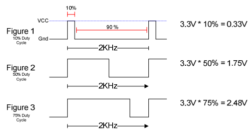
To generate the PWM waveform we use Xilinx AXI Timer. We used a dedicated timer instance for each motor to allow for independent speed control. The AXI Timer pwm output is connected to the MOTOR_EN pin on the PMODs. The State Machine is responsible for setting the total and high periods of the waveform through the AXI Timer driver from Xilinx.
You can look at the motor control implementation in the speech robot source code.
Assembling chassis
As the mechanical platform for the speech robot we selected Pololu Romi. This chassis is simple, easy to assemble and inexpensive. It also provides a built-in battery enclosure for 6 AA batteries as well as a nice power distribution board that outputs voltage sufficient for powering the motors and Arty A7 board. Pololu also provides an expansion plate for the chassis to conveniently place the Arty A7 board.
Following is a bill of material for all necessary components from Pololu.
Pololu includes an awesome video that details the process of assembling the chassis. Make sure you watch before starting to solder the power distribution board!
Before you place the power distribution board it’s time to warm your soldering iron. Solder two 8x1 headers to the VBAT, VRP, VSW terminals and the ground. You can use masking tape to keep the headers in place while soldering.

Next, place the power distribution board on the chassis so that battery terminals protrude through their corresponding holes. Use screws to secure it. Now, solder the terminals to the board.

Put the batteries in and press the power button. The blue LED should light up.
Next, solder a 6x1 headers to each of the motor encoder boards (Note! Use the same breakaway male header used with the power distribution board and not the one included with the encoder.) Then place an encoder board on each motor so that motor terminals protrude through the holes and solder them.

At last, insert motors into the chassis and wire them to HB3 PMODs (connect M- to M1 and M+ to M2). Wire the HB3 PMODs VM to one of the VSW terminals and GND to GND on the power distribution board. Plug the Arty A7 board and test everything together!
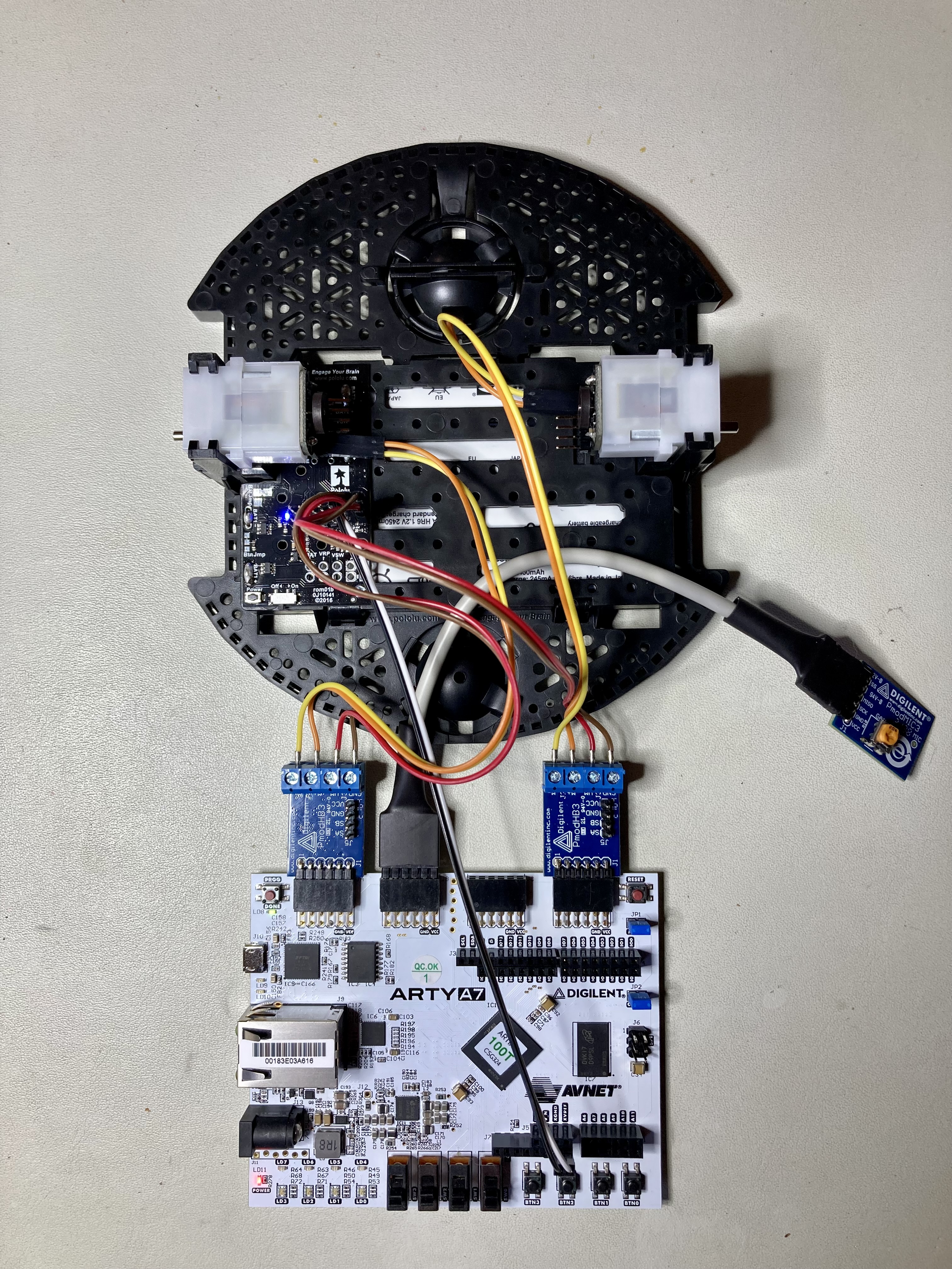
If everything works, continue with the final assembly. Connect two extension plates with 2 screws and mount it on the chassis using 4 standoffs. Mount wheels and the ball caster. Place Arty A7 board and HB3 PMODs on top of the surface formed by two extension plates. You can use two-side adhesive to keep them in place. We suggest using an 18-gauge wire to raise the MIC3 PMOD above the chassis to avoid the microphone being influenced by the noise of motors.
Conclusion
In part II of the tutorial we learned how to design the State Machine for the speech robot and how to interface with motor drivers. We then integrated all of the parts on the Pololu Romi chassis. Now that you have a functioning robot that obeys your commands, we invite you to extend it further and make use of the remaining 6 commands that our ML model can predict!